Smart Device Hardware + Wiring
This section provides an overview of what hardware is required for the smart device and how the sensors are wired to it.
Table of contents
Hardware List
- 1x Arduino Zero
- 1x Arduino Micro Jumper
- 1x NB-IoT Shield
- 1x Proto Shield Rev3 (Uno Size)
- 4x 2N7000-G Transistors
- 11x Arduino Male Pin Header
- 3x 10kΩ Resistor
- Wires
Arduino Board
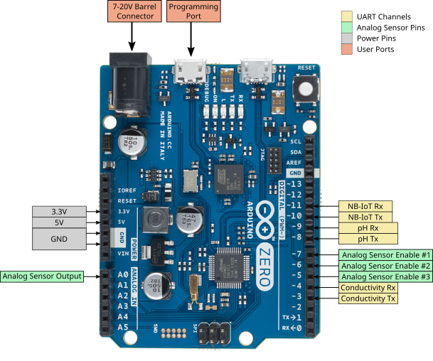
The buoy device uses an Arduino Zero board as the brain of the device. This Arduino Zero performs all processing and sensor measurements.
We will not go into the specifics of the Arduino Zero in this documentation as there are sources online. However, there are some important points that should be noted.
-
The Arduino Zero can only handle voltages of 3.3 volts and lower, any voltage greater than this will fry the board.
- The Arduino Zero does not have persistent memory, unlike the Arduino Uno.
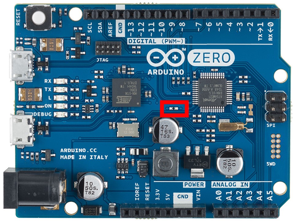
The Arduino Zero includes a debugger chip, however this chip, even when off, draws too much power. To minimize the power draw for the Arduino Zero a jumper is soldered to the Arduino Zero to completely cut power to the debugger chip.
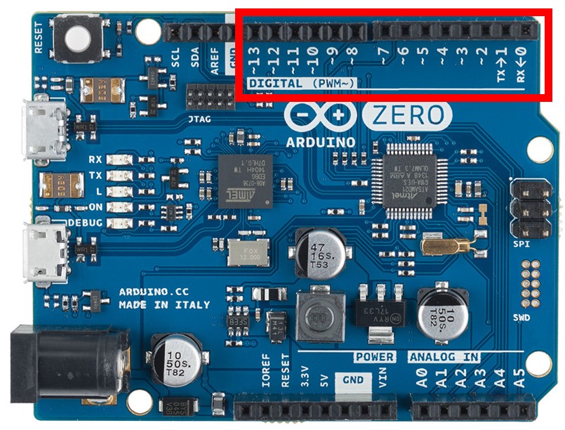
To enable the debugger chip, the 0Ω resistor highlighted on the image below must be shorted. The jumper allows this circuit to be cut, which would completely cut power to the debugger chip.
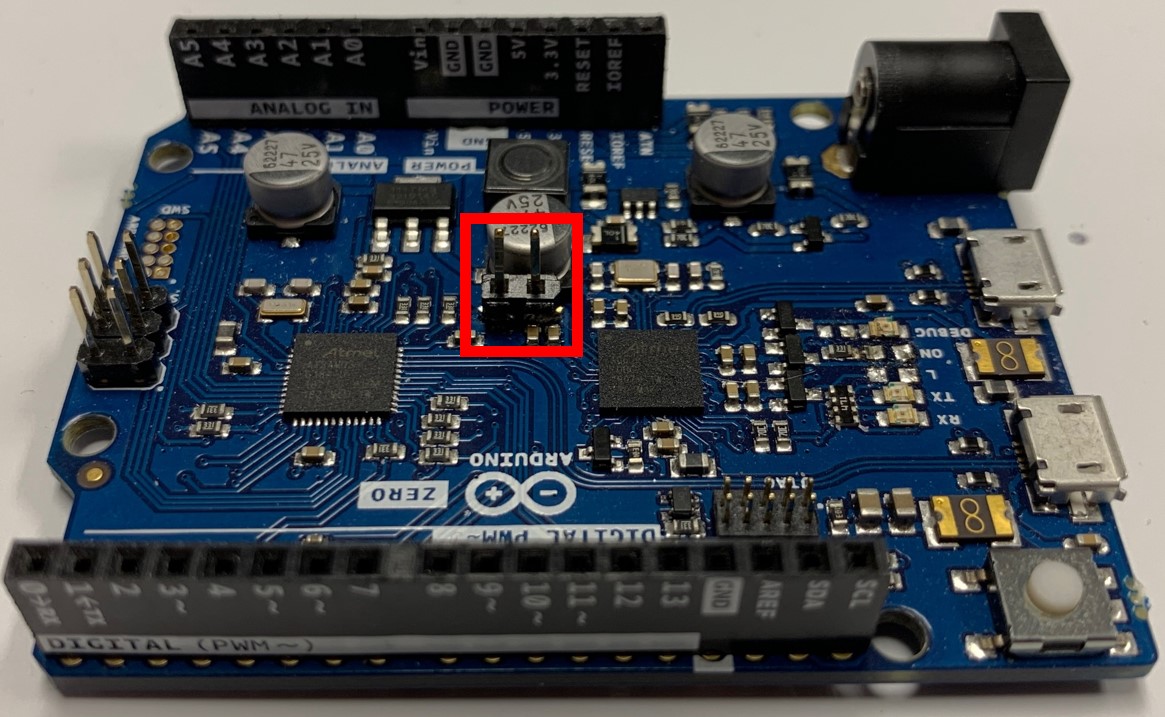
Once the jumper receiver is successfully soldered on, the board should look like below:
With this receiver now attached, the Arduino Micro Jumper, shown below, can be used to enable the debugger chip.
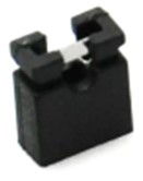
WARNING: The debugger chip must be enabled when the Arduino Zero is first turned on. Once the Arduino Zero has been flashed and turned on, the jumper can be removed, and the debugger chip disabled to save power.
NB-IoT Shield
The module that allows the buoy device to send data and communicate with the cloud is the NB-IoT shield.
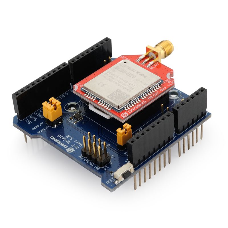
This shield rests on top of the Arduino Zero as a standard shield, connected by the pins sticking out the bottom of the shield.
This shield uses some of the pins on the Arduino Zero to function.
These pins cannot be used for any other purpose and attempting to do so will likely fry the board.
With regards to wiring the sensors, the particular pins that care should be taken to avoid are the Digital pins 10 and 11.
Further information can be found here: https://github.com/dragino/NB-IoT
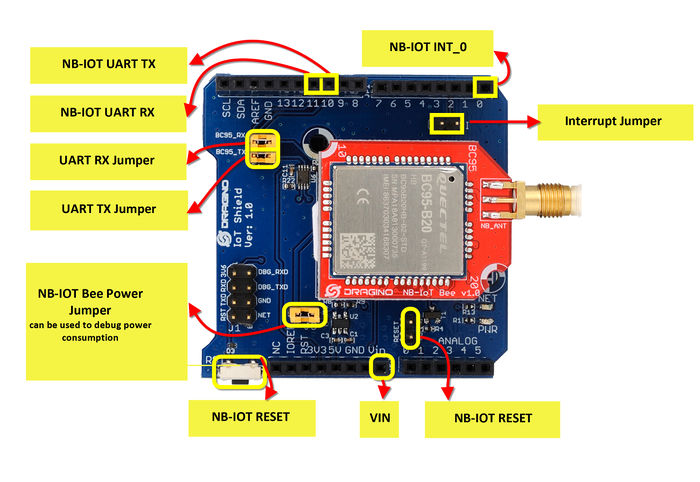
Power Saving Mode
The narrowband network has a power saving mode that NB-IoT shield can use to draw less power. However, this power saving mode has specific periods for sleep and wake time.
As such, a GPIO (General Purpose Input / Output) pin is used to wake up the NB-IoT shield for transmitting.
However, there is no way to access the power key pin, which will wake up the NB-IoT shield for transmissions, normally.
To access this pin, a wire must be attached (soldered) to the bottom of the NB-IoT shield.
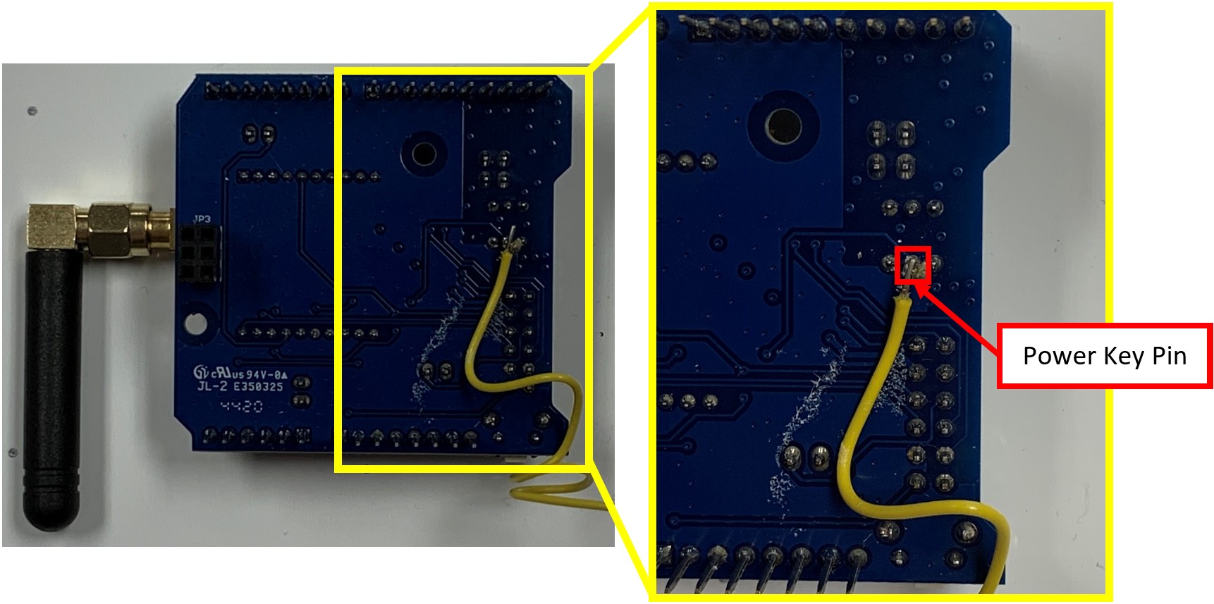
The middle pin of the middle three pin set, highlighted above, is linked to the NB-IoT module power key pin.
The other end of the wire should be plugged into digital pin 12.
Digital pin 12 was coded to power on the NB-IoT module. However, this pin is not special, any pin could be set to power on the NB-IoT module.
Narrow Band Sim Card for Rogers Network
The NB-IoT module has been setup to use a Rogers Narrow Band Sim Card.
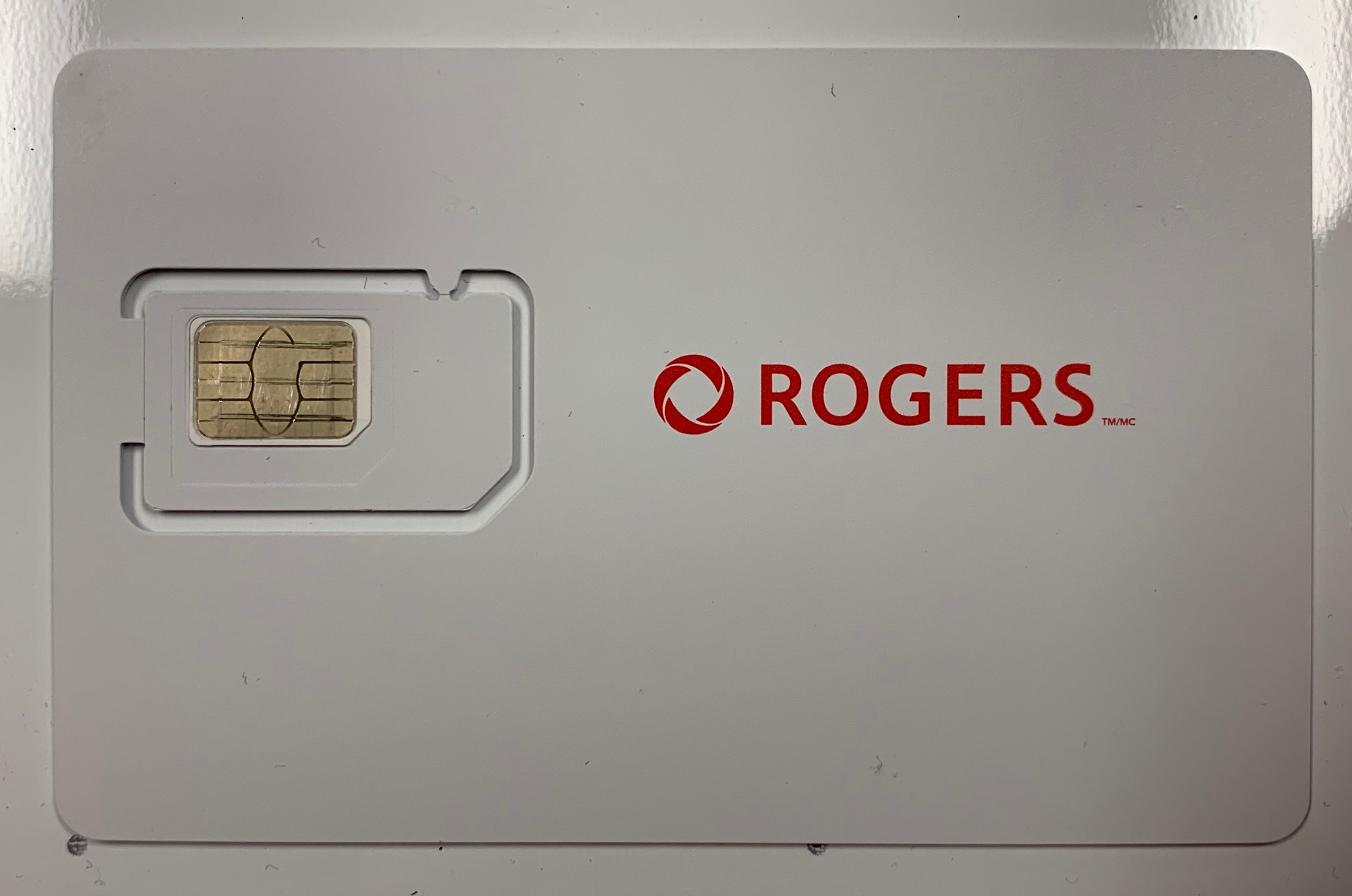
The sim cards must follow the following format, 89302820… . The 820 part of the number is the important part.
If the sim card has the following format, 89302720… . Then the sim card will connect to the LTE M1 Network for Rogers. This network does not have PSM (Power saving mode) or E-I-DRX (Extended Idle Discontinuous Reception), all of which is needed for power saving on the device.
PERF Shield
To organize the wiring and create the appropriate sensor circuits, an Arduino PERF shield is used.
An image of the PERF shield circuitry can be seen below.
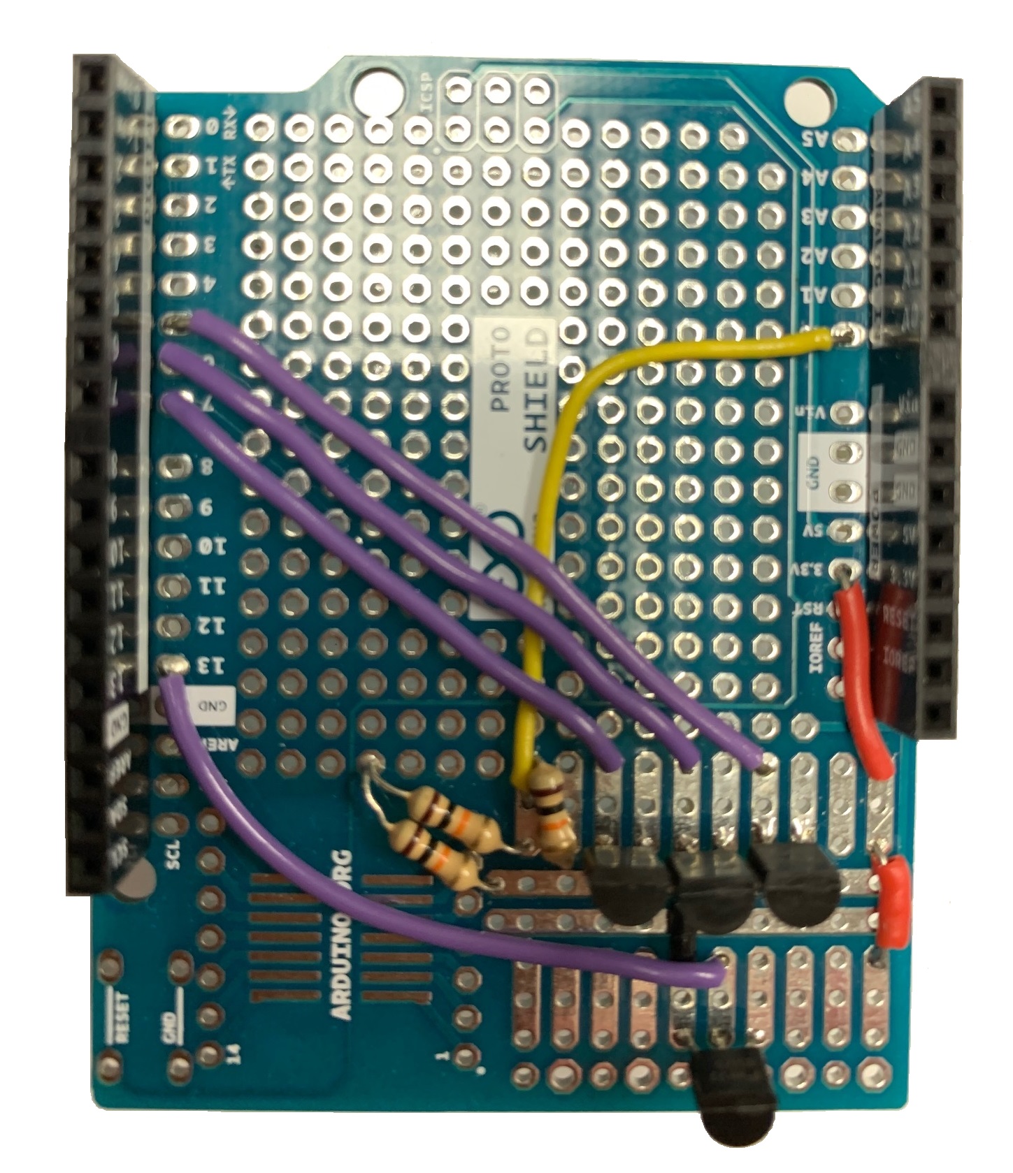
As identified on the image above, the PERF Shield has hardware for various purposes.
The board uses four transistors to turn off and on the more power-hungry sensors. By using one of the digital pins to supply voltage to the transistor, power from the constant power supply pins can be controlled.
Additionally, a group of resistors act as a voltage divider, downscaling the return voltage of the turbidity sensor from the max 4.5 volts to a max 3.0 volts. This is essential as the turbidity sensor requires 5.0 volts to operate and the return voltage of 4.5 volts is above the maximum 3.3 volts that the Arduino Zero can accept without frying the board.
PERF Shield Wiring
The PERF Sheild is where all the sensors are wired to the device.
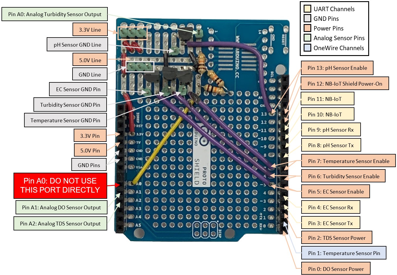
The image above shows the pins and important locations on the PERF shield where the sensors are wired.
Some sensors can only be wired to the specific pins, while other sensors can be moved.
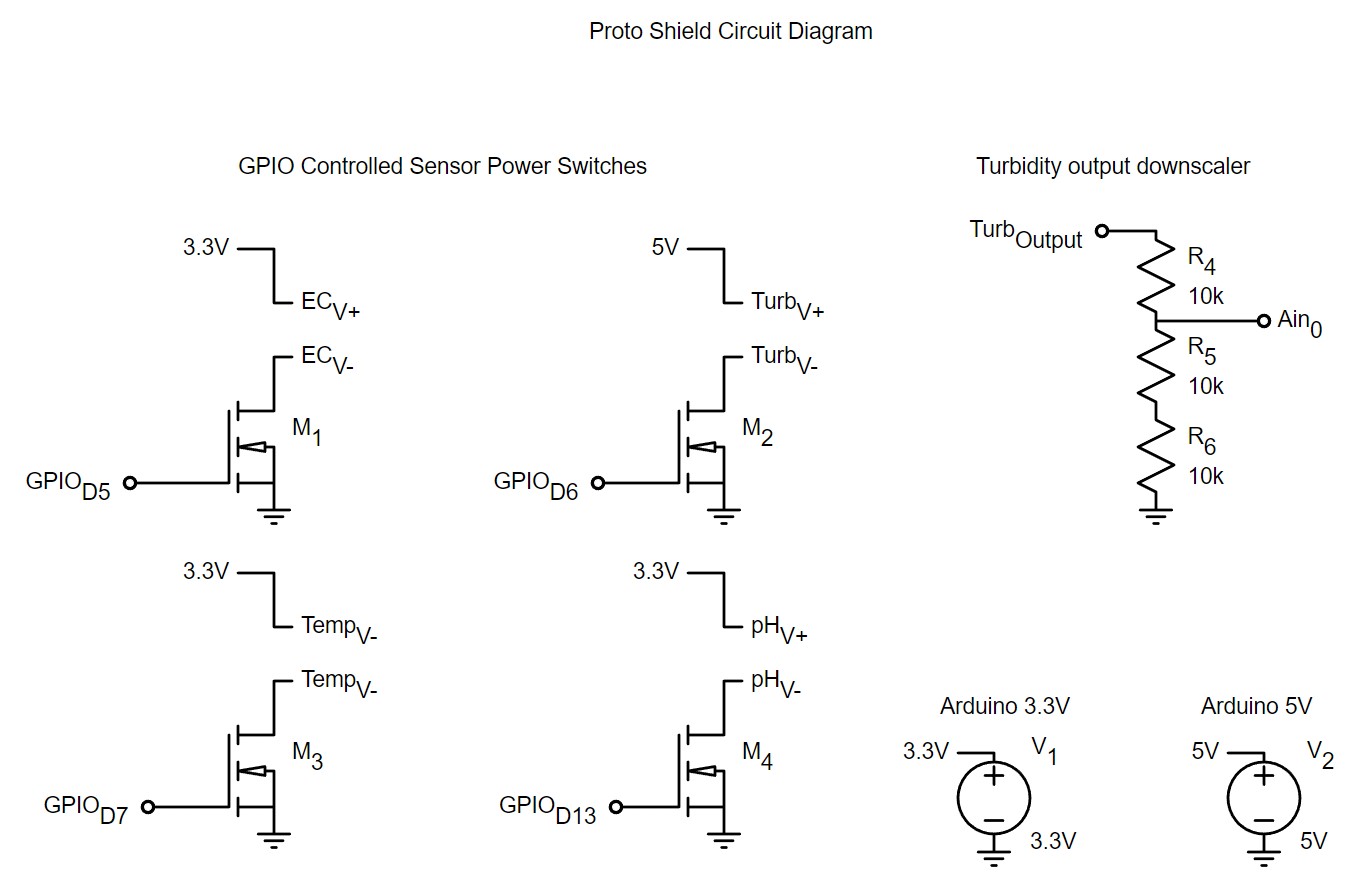
The circuit diagram for the perf shield can be seen above. This diagram can be used to properly wire the current sensors.
General Sensor Wiring
There are three main types of sensors being used, analog, OneWire, and UART sensors.
Analog Sensor
The Arduino Zero has 6 built-in analog ports that can be used to take analog sensor measurements directly.
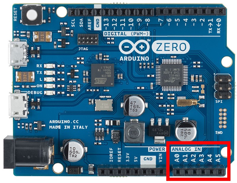
The reading wire of the Analog sensors would plug into one of these ports.
Most analog sensor connector cables have 3 wires, the power wire (red), the ground wire (black), and the reading wire (other colour), that needs to be connected to the board to take analog measurements.
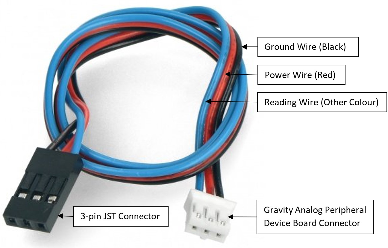
The wire shown above is a connector cable between an Arduino Board and a Gravity Analog Peripheral Device Board.
Example Sensor Wiring
To take a single analog sensor’s measurement, you can directly wire the sensor to the pins on the board.
For example, below is a diagram displaying a single sensor with readings being taken on Analog Pin 0.
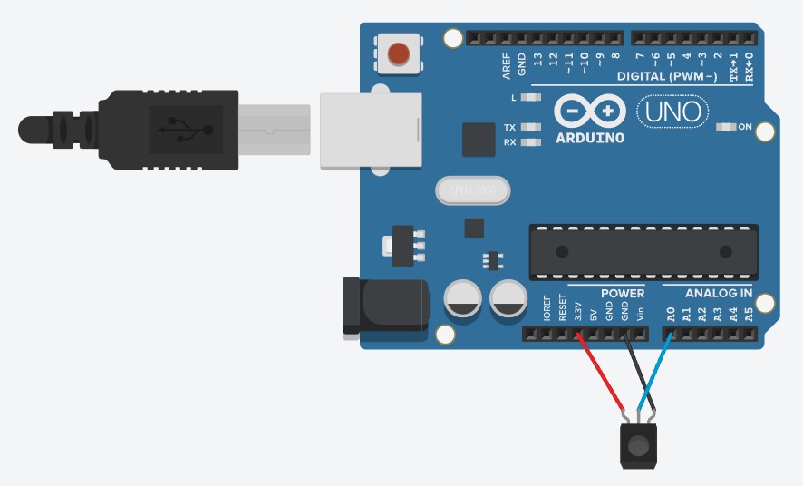
Note: the Arduino board displayed in the diagram is an Arduino Uno, not an Arduino Zero. However, regarding the wiring configuration, the Arduino Uno and Zero are the same.
As you can see the sensor is powered by the 3.3 Volt pin and connected to the ground pin. The 3.3V pin is used as the 5V pin would fry an Arduino Zero.
OneWire Sensor
The one wire protocol uses a single wire interface for data communication between devices.
Devices using this protocol to communicate over the Arduino digital pins.
The Arduino Zero has 13 built-in digital ports that can be used for the OneWire Protocol.
The data wire of the OneWire sensor would plug into one of these digital pins setup for OneWire communication.
Most OneWire sensor connector cables have 3 wires, the power wire (red), the ground wire (black), and the data wire (other colour), that needs to be connected to the board for OneWire communication.
The wire shown above is a connector cable between an Arduino Board and a Gravity Terminal Sensor Adapter V2.0 Board, such as needed by the OneWire Gravity: Waterproof DS18B20 Sensor.
UART Sensor
UART is a hardware communication protocol that uses asynchronous serial communication with configurable speed.
Devices using this protocol communicate using two Arduino digital pins, a Rx and a Tx pin for receiving and transmitting messages.
The Arduino Zero has 13 built-in digital ports that can be used for the OneWire Protocol.
Most Atlas UART sensors use an Electrically Isolated EZO™ Carrier Board. This board has 5 pins, the VCC pin for power, the OFF pin, the GND pin connects to ground, the Rx pin connect to the Tx port of the Arduino board, and the Tx pin connect to the Rx port of the Arduino board.
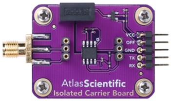
This carrier board is where the sensor specific EZO board would be placed, and where the sensor probe would be connected.
Wiring Multiple Sensors
To measure multiple sensors, you will need to create a simple circuit, using a breadboard during development or a perf board for the actual device.
For example, below is a diagram displaying two sensors connected to a breadboard, with reading being taken on Analog Pin 0 and 5.
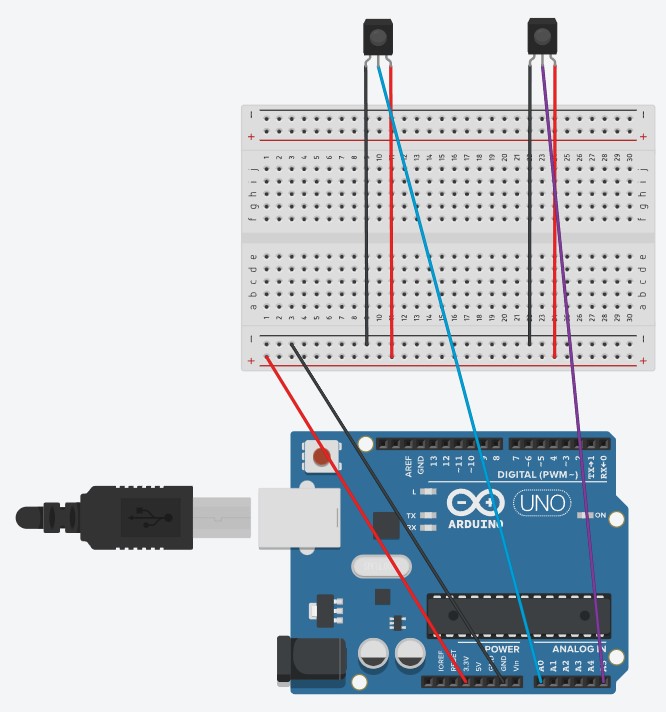
Note: the Arduino board displayed in the diagram is an Arduino Uno, not an Arduino Zero. However, regarding the wiring configuration, the Arduino Uno and Zero are the same.
As you can see power is being supplied to the breadboard by the 3.3 Volt pin, with the second line grounded. The two sensors then branch off those lines, with their respective reading lines connected to the Arduino analog pins.